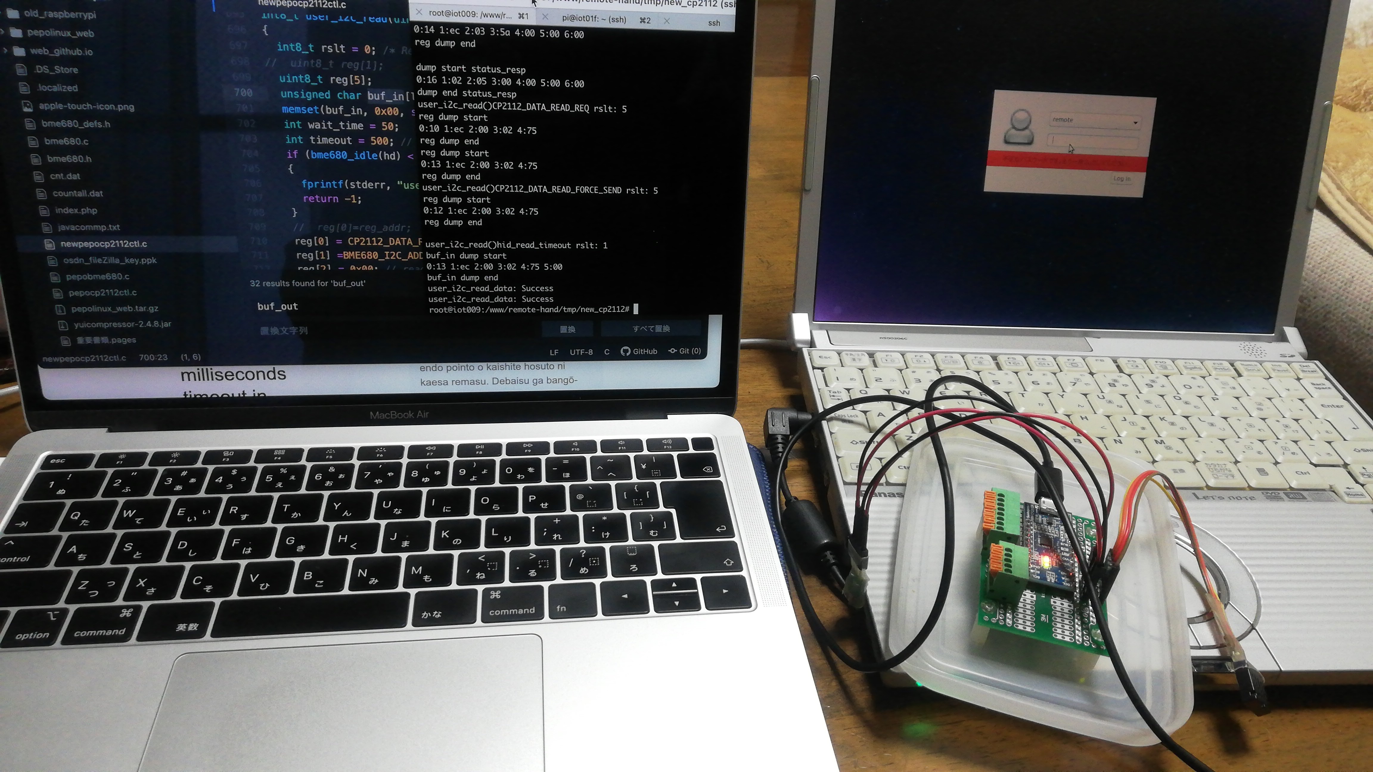
cp2112_BME680
What is CP2112?
USB<->I2C conversion chip (Silicon Laboratories Single-Chip HID USB to SMBus Master Bridg) for Linux and Windows USB You can use 8 GPIOs and I2C from, here we are using the module board of Sunhayato’s MM-CP2122A.
MM-CP2122A Selling phraseI2C connection sensor and GPIO (8 pin) can be controlled directly from a PC application without programming the microcomputer. is a difficult task, and programming requires an understanding of the HIDAPI and CP2112 interface specifications below.
- Hidapi Reference
- CP2112 Reference AN495: CP2112 Interface Specification
- I2C connection device verified this time BME680 hardware data
When I connect to the USB of my lubuntu lts 18.04 Linux machine, the driver is loaded as shown below and the HID device is recognized.
1
2
3
4
5
# lsmod |grep cp2112
hid_cp2112 24576 0
hid 102400 3 hid_cp2112,hid_generic,usbhid
# ll /dev/hidraw-cp2112
lrwxrwxrwx 1 root root 7 4月 6 16:54 /dev/hidraw-cp2112 -> hidraw0From here, we verified the operation of GPIO and I2C connection temperature/humidity sensor AM2320 and environmental gas sensor BME680 based on the above materials and collected information pepocp2112ctl.cThe explanation is based on the program.

Install the package for development
libhidapi1
2# apt install libhidapi-dev
libhidapi-dev libhidapi-hidraw0 libhidapi-libusb0Get and compile the following filesFork from BoschSensortec/BME680_driver
1
2
3
4
5
6
7
8
9
10
11bme680.c bme680.h bme680_defs.h pepocp2112ctl.c
# gcc -Wall -o pepocp2112ctl pepocp2112ctl.c bme680.c -lhidapi-hidraw
# ll
total 144
drwxr-xr-x 2 root root 140 4月 6 17:39 ./
drwxr-xr-x 3 www-data www-data 840 4月 6 17:39 ../
-rwxr-xr-x 1 root root 44364 4月 13 2019 bme680.c*
-rwxr-xr-x 1 root root 8353 4月 13 2019 bme680.h*
-rwxr-xr-x 1 root root 17134 4月 13 2019 bme680_defs.h*
-rwxr-xr-x 1 root root 34644 4月 6 17:39 pepocp2112ctl*
-rw-r--r-- 1 root root 30626 3月 28 16:26 pepocp2112ctl.cProgramming example, SMBus Devices operation only Extract from source and explain only important parts, check the source for others. (Experience shows that GPIO needs to be operated in multiple processes, so there is a considerable amount using semaphore.)
- CP2112’s I2C connection device BME680 sets the I2C address, required commands, data, and byte counter in the buffer, sends it with hid_send_feature_report, and waits for a response to the command if necessary.
- The BME680 write sets the command(CP2112_DATA_WRITE), register address, data, and number of bytes and writes it to the device.
1
2
3
4
5
6
7
8
9
10int8_t user_i2c_write(uint8_t dev_id, uint8_t reg_addr, uint8_t *reg_data, uint16_t len)
{
.
reg[0] = CP2112_DATA_WRITE;
reg[1] = BME680_I2C_ADDR_PRIMARY<<1;
reg[2] = len+1;
reg[3] = reg_addr;
for (int8_t i=4; i<len+4; i++)
reg[i] = reg_data[i-4];
rslt = hid_send_feature_report(hd, reg, len+4);- Dump of buffer etc. during debugging
1
2
3
4
5user_i2c_write() dev_id: ec reg_addr: e0 len: 1
user_i2c_write()1 rslt: 5 len: 1
reg dump start
0:14 1:ec 2:02 3:e0 4:b6
reg dump end
- Dump of buffer etc. during debugging
- The BME680 read first sends the register address with a write command.
Next, send the I2C address read request command(CP2112_DATA_READ_REQ),Wait for Polling, status confirmation(CP2112_DATA_READ_RESPONS),until the data is ready(CP2112_DATA_READ_FORCE_SEND),and then read the data from the device.1
2
3
4
5
6
7
8
9
10
11
12
13
14
15
16
17
18
19
20
21
22
23
24
25
26
27
28
29
30
31
32
33
34
35
36
37
38
39
40
41
42
43
44
45
46
47
48
49
50
51
52
53
54
55
56
57
58
59
60
61int8_t user_i2c_read(uint8_t dev_id, uint8_t reg_addr, uint8_t *reg_data, uint16_t len)
{
.
reg[0] = CP2112_DATA_WRITE;
reg[1] = BME680_I2C_ADDR_PRIMARY<<1;
reg[2] = 1;
reg[3] = reg_addr;
rslt = hid_send_feature_report(hd, reg, 4);
.
user_delay_ms(HID_WAIT);
reg[0] = CP2112_DATA_READ_REQ;
reg[1] = BME680_I2C_ADDR_PRIMARY<<1;
reg[2] = 0x00; // reads length_high
reg[3] = len; // reads length_low
rslt = hid_send_feature_report(hd, reg, 4);
.
user_delay_ms(HID_WAIT);
while (retry_cnt < 3)
{
/* SMBus Polling */
reg[0] = CP2112_DATA_READ_FORCE_SEND;
reg[1] = 0x00; // reads length_high
reg[2] = len; // reads length_low
rslt = hid_send_feature_report(hd, reg, 3);
.
user_delay_ms(HID_WAIT);
rslt = hid_read_timeout(hd, buf_in, len+3, timeout);
.
/*
buf_in[0]:hid_report ID->0x13:CP2112_DATA_READ_RESPONS
buf_in[1]:hid_status 0x00->Idle ,x01->Busy ,x02->Complete
,buf_in[2]:hid_read_length
buf_in[3]-:Following_BME680_Read_Data
*/
if (buf_in[0] == CP2112_DATA_READ_RESPONS)
{
if (buf_in[1] == 0x00 || buf_in[1] == 0x02 || buf_in[1] == 0x03)
.
break;
retry_cnt++; // Busy or Idle or Other
user_delay_ms(HID_WAIT);
continue;
}
if (buf_in[0] == CP2112_TRANSFER_STATUS_RESP)
{
.
user_delay_ms(HID_WAIT);
retry_cnt++;
continue;
}
}
.
if(buf_in[2] > 0 && rslt > 3 && buf_in[2] < rslt)
{
int8_t j = buf_in[2];
for (int8_t i=0; i < j; i++)
{
reg_data[i] = buf_in[i+3];
}
return 0;
}- Dump of buffer etc. during debugging
1
2
3
4
5
6
7
8
9
10
11user_i2c_read dev_id: ec reg_addr: d0 reg_data: 04 len: 1
user_i2c_read()hid_read_timeout rslt:4 retry_cnt:0
buf_in dump start
0:13 1:02 2:01 3:61
buf_in dump end
user_i2c_read dev_id: ec reg_addr: 89 reg_data: 04 len: 25
user_i2c_read()hid_read_timeout rslt:28 retry_cnt:0
buf_in dump start
0:13 1:02 2:19 3:40 4:a3 5:66 6:03 7:2f 8:80 9:8e 10:c9 11:d6 12:58 13:ff 14:de 15:19 16:cf 17:ff 18:2f 19:1e 20:00 21:00 22:1a 23:f3 24:e7 25:f6 26:1e 27:02
buf_in dump end
- Dump of buffer etc. during debugging
Please check the source code below
https://github.com/kujiranodanna/BME680_driver